Awesome House Plans Electrical Symbols
Symbol encoding effectively transfers 2.286 bits per symbol compared to 1.0 bits per lane for D-PHY. The first version of C-PHY (v1.0) operates at 2.5GHz, same as the D-PHY V1.2. A four lane D-PHY V1.2 provides 10Gbps which enables: • 4K video at 30fps • 1080p at 120fps A 3 channel C-PHY provides 17Gbps which enables: • 4K video at 60fps
PHC Facility Management Electricity Definition, Units, Sources
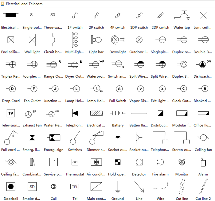
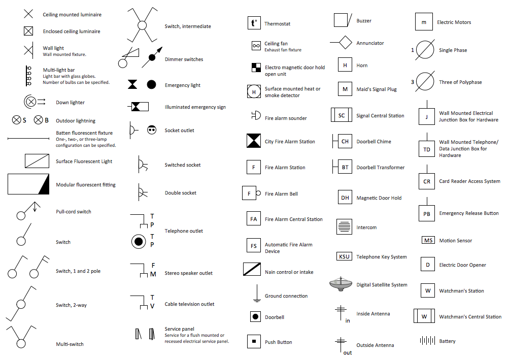
These symbols represent electrical outlets, switches, lights, and other components that are found in a typical residential wiring system. Understanding these symbols is essential for any homeowner or aspiring electrician who wants to be able to read and interpret electrical blueprints and diagrams.
Electrical Symbols for House Plans
Transformers, Generators, and Motors: These larger components of the electrical system have their own distinct symbols, usually consisting of a circle with specific letters or symbols inside to represent their function. Understanding their Interplay

List Of Electrical Materials Used For Residential Building lceted
The completed plan needs to be a detailed, accurate representation of the house and the electrical system. It should also incorporate the use of well-known or commonly used electrical symbols so that professional electricians and other contractors are able to use the plan as a reference for any renovation projects. Use this guide to learn how.

House Electrical Plan Software Electrical Diagram Software
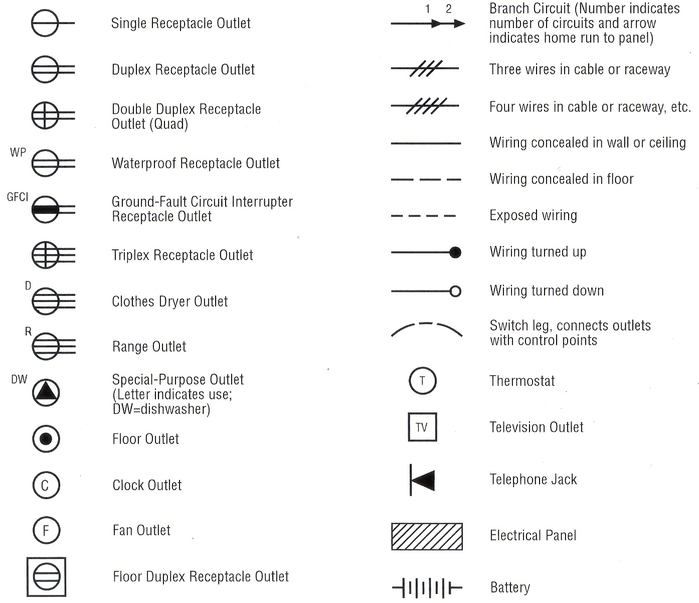
Preview Course Common Electrical and Lighting Symbols 1. Duplexes A circle off of the wall and connected to it by two parallel lines represents a typical outlet (or receptacle) with two sockets. Abbreviations and numbers next to the duplex provide additional information.

House Electrical Plan Software Electrical Diagram Software
Example 2. Electrical Symbols Electric and Telecom Plans Solution contains also collection of already predesigned templates and samples which can be used as the good base for various electrical and telecom plans. Example 3. Home Electrical Plan Sample

Electrical Symbols Drawing at GetDrawings Free download
1. What is a House Wiring Diagram? A wiring diagram is a pictorial representation of an electric circuit, where the elements of the loop and the signal connections between devices and the power source are shown in the conventional methods as simplified shapes. A house wiring diagram is thus, a wiring diagram of a house.

House Electrical Plan Software Electrical Diagram Software
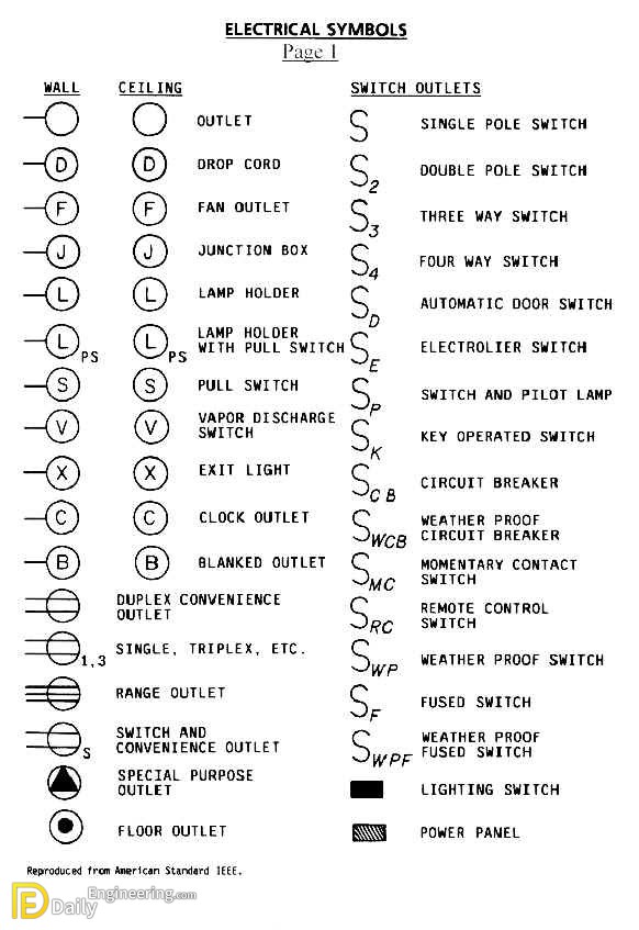
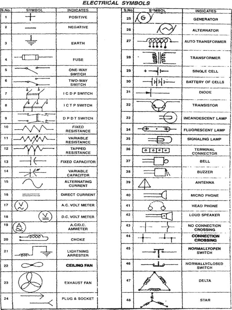
The most commonly used electrical blueprint symbols including plug outlets, switches, lights and other special symbols such as door bells and smoke detectors are shown in the figure below. Note: Explanations for common household electrical items such as three-way switches and switched duplex plug outlets are below the figure. Notes:

Electrical symbols residential Drawing. Download free in Autocad.
By John Peter | July 8, 2023 0 Comment Unlocking the Mystery of House Electrical Symbols If you're a homeowner looking to do DIY wiring or repair work, you'll likely find yourself stumped by the different electrical symbols used on wiring diagrams.
Electrical House Plan details Daily Engineering
A typical set of house plans shows the electrical symbols that have been located on the floor plan but do not provide any wiring details. It is up to the electrician to examine the total electrical requirements of the home especially where specific devices are to be located in each area and then decide how to plan the circuits.

Electrical symbols Drawing. Download free in Autocad. DwgFree
Based on the basic floor plan structure, a house wiring diagram is supposed to add more than just electrical symbols. As a matter of fact, a complete house wiring plan usually includes common electrical symbols such as lighting, switches, and sockets, as well as basic floor plan symbols such as walls, furniture, and home appliances.
Home Electrical Plan, Electrical Symbols
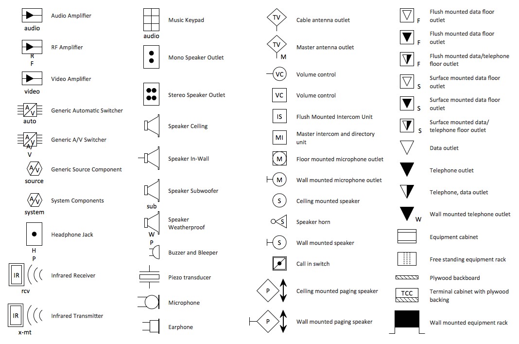
Receptacles Grounds Irrigations Motors Boxes Transformers Fuses Transients These symbols are all used to represent different electrical components, and you may find them in any kind of wiring diagram. Additionally, some symbols may look the same but have different meanings depending on the type of wiring diagram. How to Read Wiring Diagrams
HOUSE WIRING_intro Ourengineeringlabs
Step 2: Add Electrical Floor Plan Symbols. When the basic floor plan is complete, drag and drop electrical symbols onto the layout, including various lighting fixtures, fans, switches, and outlets. RoomSketcher lets you customize each element's size, placement, and orientation. It's a good idea to add labels and notes for further clarification.

Architectural Drawing Symbols PrintMyDrawings
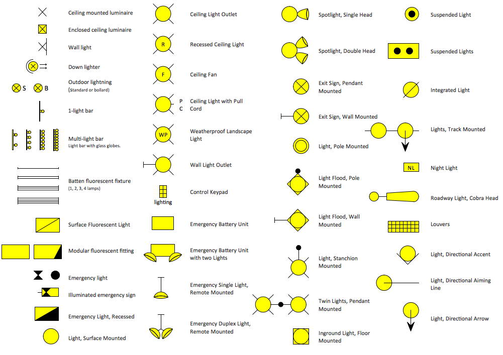
These symbols, which are drawn on top of the floor plan, show lighting outlets, receptacle outlets, special purpose outlets, fan outlets and switches. Guidelines to basic electrical wiring in your home and similar locations (on image: An example of electrical plan - click to expand)
House Electrical Plan Software Electrical Diagram Software
Switches (S or SW) are electrical components that can connect or disconnect the conducting path in an electrical circuit. They also can change the path of the current flow. Symbols can indicate the difference between toggle or push-button switches and whether they are in the On or Off position. Resistors (R) restrict the flow of electrical current.

electrical symbols Home electrical wiring, Electricity, Electrical
Electrical Plan Symbols Design & Documentation > Construction Documentation Every engineering office uses their own set of electrical symbols; however, the symbols below are fairly common across many offices. Refer to the legend sheet in your set of plans for special symbols used in a particular set. Article Contents Power Symbols Lighting Symbols